


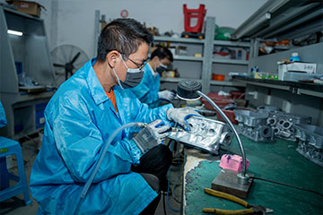
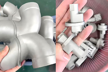
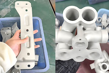
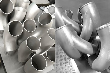

Let’s cut straight to it: most teams new to 3D printed copper cooling make the same avoidable mistakes. They take a design built for machining or brazing, send it over to print, and end up with a part that warps, clogs with powder, fails pressure testing, or just doesn’t hit the thermal performance they expected.
3D printing unlocks way more design freedom than traditional manufacturing — but it still has rules. Ignore them, and you’ll waste weeks iterating and thousands of dollars on bad prototypes. Get them right, and you can build coolers that outperform anything you could make with old methods.
This guide pulls together the real-world DFM (Design for Manufacturing) rules we use every day to review client designs. No theoretical lab specs, no marketing fluff — just production-grade guidelines you can actually design to. This guide is part of our full lineup of 3D printed copper & copper alloy thermal management solutions, so you can see how design best practices fit into the bigger picture.
Сначала: Shift Your Mindset From “Machinable” to “Additive-Optimized”
If you’re used to designing for milling, extrusion, or brazing, this is the single biggest mindset shift you need to make.
Traditional manufacturing works by removing material. You start with a solid block of copper and cut away what you don’t need. That forces you into straight channels, uniform walls, and flat, external features — because anything curved or internal is either impossible or prohibitively expensive.
3D printing works by building material layer by layer. Suddenly, curved flow paths, internal lattices, variable wall thickness, and hotspot-targeted cooling are all on the table. You can design for thermal performance first, then tweak for printability.
The catch: you can’t just port a machined design over and expect great results. Additive manufacturing has its own constraints around overhangs, support removal, wall strength, and powder clearance. The best designs lean into 3D printing’s strengths while working within its real-world limits.
Core Design Specs You Can Actually Build To (No Theory, Real Production Numbers)

These are the baseline specs we design to for production-grade copper thermal parts. These aren’t lab-only one-off numbers — these are the features we can print consistently, batch after batch, with reliable quality.
Минимальная толщина стенки
For production parts, we reliably print 0.2mm thick walls in both pure copper and copper alloys. Итак,, thinner walls are more fragile, especially in pure copper. If your part will see handling, assembly, or pressure, we recommend 0.3mm or thicker for pure copper, and 0.25mm+ for higher-strength copper alloys. We always flag walls that are too thin for your operating conditions during DFM review.
Minimum internal microchannel diameter
We consistently print 0.3mm diameter internal channels at production scale. Below that size, powder removal gets tricky, and the risk of clogging goes up. For liquid cooling designs, we almost always recommend 0.4mm+ channels for most applications to leave margin for post-processing and reliable operation.
Minimum lattice strut diameter
For TPMS lattice structures, we can print struts down to 0.15mm diameter on appropriately sized parts. For production parts that need consistent strength and thermal performance, we typically recommend 0.2mm+ struts to account for normal process variation and ensure long-term reliability.
Overhangs and self-supporting angles
As a rule of thumb, any surface steeper than 45° from horizontal will need support structures to print correctly. For internal cooling channels, round cross-sections are your friend. A perfectly round hole will self-support on the top half and only need supports on the flat bottom. If you can tilt channels at an angle, you can often eliminate supports entirely.
Threaded ports and mounting features
You can absolutely add threaded ports, mounting holes, and alignment features to 3D printed copper parts. For pure copper, we usually recommend tapping threads after printing rather than printing them directly, since the softer material can deform easily. For copper alloys like CuCrZr, direct-printed threads work well for most low-torque applications.
Design Best Practices By Cooling Structure Type
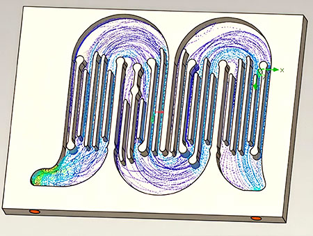
Microchannel cold plates
Dense microchannels deliver great heat transfer, but they’re easy to get wrong.
- Balance channel density with pressure drop. Подробнее, smaller channels = more surface area, but also higher flow resistance. Don’t optimize for surface area in a vacuum — always tie it back to your system’s available flow rate and pressure budget.
- Use gradual transitions between inlet/outlet manifolds and channels. Sudden diameter jumps create turbulence, dead zones, and unnecessary pressure drop.
- Keep wall thickness consistent where possible. Uneven walls can cause uneven cooling and thermal stress during operation. For real-world examples of optimized microchannel designs, see our full guide to 3D printed copper liquid cold plates for server cooling.
TPMS lattice structures

Lattices deliver the highest surface area per unit volume, but they require careful tuning.
- Match cell size to your flow conditions. Too small, and pressure drop skyrockets. Too large, and you’re wasting volume.
- Vary density across the part. Use denser cells directly over hotspots, and more open cells in cooler areas. You’ll get better performance without driving up overall pressure drop.
- Plan for powder removal. Lattices with fully interconnected flow paths are much easier to clean out than closed or partially closed geometries. We break down full performance comparisons for different lattice types in our guide to TPMS lattice porous cooling structures.
Conformal and complex flow paths
Conformal channels that follow your heat source shape are one of the biggest advantages of 3D printing — if you design them right.
- Avoid sharp 90° turns. They cause flow separation, dead zones, and unnecessary pressure drop. Use curved, gradual bends instead.
- Keep flow velocity consistent across the entire path. Widening and narrowing channels too abruptly creates uneven cooling and thermal stress.
- Account for material strength. Thin walls in high-pressure curved sections can bulge or fail over time. If you’re running high pressure, a copper alloy will let you use thinner walls than pure copper without sacrificing durability. We compare material performance for fine features in our full pure copper vs copper alloy 3D printing comparison guide.
Thin-fin air-cooled heat sinks
For air-cooled IGBT and power electronics designs, 3D printing lets you build fin geometries you can’t extrude or skive.
- Taper fins from base to tip for better strength and printability.
- Use pin fins or staggered patterns instead of straight parallel fins to promote turbulent airflow and better heat transfer.
- Don’t make fins too tall relative to their thickness. Tall, thin fins in pure copper are prone to bending during handling and operation. See real-world applications in our guide to 3D printed copper IGBT heat sinks for power electronics.
Material Choice Impacts Your Design More Than You Think

Your material selection doesn’t just change thermal performance — it changes what geometries are practical, how thick walls need to be, and what post-processing steps work best.
Pure copper delivers maximum thermal conductivity (390–410 W/m·K), but it’s softer. That means you’ll need slightly thicker walls for the same pressure rating, and you’ll want to plan for secondary tapping for threaded ports instead of printing them directly. It’s perfect for static, low-to-medium pressure applications where raw cooling performance is the top priority.
Copper alloys like CuCrZr have slightly lower conductivity (320–350 W/m·K) but much higher strength and hardness. You can print thinner walls for high-pressure designs, use direct-printed threads, and get better vibration and fatigue resistance. They’re the go-to for automotive, промышленный, and high-pressure liquid cooling systems.
If you’re still weighing material options, our side-by-side comparison guide walks you through performance, стоимость, and use cases to help you pick the right one the first time.
Отзывы зарубежных B2B-клиентов

“Я очень боялся, что случится что-то плохое. Но после получения товара, Я понял, что мои опасения были совершенно напрасны. DT 3D Printing — это очень надежный завод с гарантированным качеством.”


“Качество продукта на высшем уровне – notch, мастерство исполнения просто восхитительно, качество печати отличное, а доставка происходит очень быстро. В целом, это отличное соотношение цены и качества, и я очень доволен.”


“Качество печати просто отличное, и цена вполне доступная. Скорость доставки тоже высокая. В общем, DT — это надежный завод, и мы будем продолжать с ними сотрудничать в долгосрочной перспективе.”



The Most Common Design Mistakes We See (And How To Avoid Them)
We review dozens of copper cooling designs every month, and the same mistakes pop up over and over. None of them are dealbreakers, but catching them early saves you time and money.
Sharp internal corners
Sharp 90° angles inside flow channels cause two problems: they create stress concentrations that can crack under thermal cycling, and they cause flow separation that kills heat transfer efficiency. Add generous radii to all internal corners — it costs nothing and improves both performance and reliability.
No plan for support removal
It’s easy to design a cool internal structure, but if you can’t get the support material and loose powder out, it’s useless. Always leave access holes for powder removal and support cleanup, especially for long, narrow channels. We can help you plan access points that don’t impact cooling performance.
Over-optimizing for surface area, ignoring pressure drop
We see this all the time: teams cram as many channels or as dense a lattice as possible into a footprint, only to find out their pump can’t push enough coolant through it. Always design to your system’s actual pressure and flow limits, not just maximum surface area. A slightly less dense design that works with your existing pump will almost always outperform a denser one that starves for flow.
Designing for machining, not 3D printing
Extra chamfers, unnecessary flat faces, and uniform wall thickness everywhere made sense for milling. For 3D printing, they just add print time and cost without any benefit. Don’t add features just because you’d add them on a machined part — design only what you need for performance and assembly.
Forgetting thermal interface surfaces
The flat mounting surface that bolts to your component matters. We recommend leaving extra stock on mating surfaces, then finish-machining them flat after printing. As-printed surfaces are smooth enough for many uses, but for minimal thermal resistance, a machined flat face is always worth it.
Don’t Forget Post-Processing In Your Initial Design
Printing is only half the process. How you design your part directly impacts how easy it is to post-process — and how well it performs in the end.
- Удалить поддержку: Plan for where supports will attach to your part, and leave enough clearance to remove them without damaging fine features.
- Отделка поверхности: If you need polished internal channels or smooth external surfaces, account for slight material removal in your nominal dimensions.
- Термообработка & HIP: All of our pure copper parts get a standard heat treatment to maximize conductivity. For parts needing zero internal porosity, we offer HIP (Горячее изостатическое прессование). Both processes cause minimal dimensional change, but we factor that in during design review.
- Pressure & leak testing: For liquid cooling parts, always design with pressure testing in mind. We’ll flag any features that could cause test failures during DFM review.
Ready To Get Your Design Reviewed For Manufacturability?
Skip the guesswork and avoid expensive prototype iterations. Send us your CAD file, thermal specs, and operating conditions, and our engineering team will give you a full, honest DFM review.
We’ll tell you what works, what won’t print reliably, where you can optimize for better performance or lower cost, and which material makes the most sense for your application. No generic sales pitches, just straight engineering feedback.
Request your free DFM design review today and get your part right the first time.
Keep exploring


О нас
1. We are a professional metal 3D printing manufacturer.
2. Мы печатаем металлические детали для автомобильной промышленности на 3D-принтере, медицина, самолет, аэрокосмическая отрасль, дрон, и судостроительной отрасли, с использованием таких материалов, как нержавеющая сталь, титан, медь, алюминий и виды сплавов.
3. Мы предлагаем комплексные услуги по 3D-печати.
Наши услуги включают:
SLM / BJ / SLA / MJF / FDM / SLS / DLP, CNC machining and post-processing
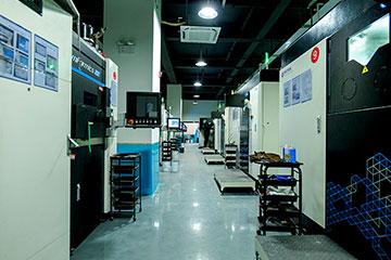
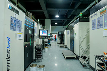
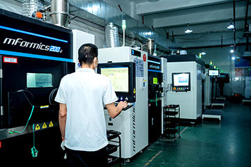
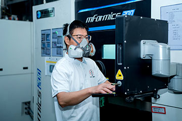
4. Мы владеем 33 3D-принтеры SLM для металла, 14 CNC machining tools, 60 3D-принтеры для печати на пластике, 50 BJ 3D printers (owned by another company in which DT has invested), и цифры продолжают расти.
5. We are a source factory for many global 3D printing service providers.
Почему стоит выбрать нас?
- We have helped customers design and manufacture numerous pure copper and copper alloy thermal management components with SLM 3D printing using copper and copper alloys for clients all over the world.
- Мы предлагаем собственное производство с 33 high-end industrial SLM metal 3D printers, 14 Станки с ЧПУ и 50 industrial BJ 3D printers (Owned by another factory in which we have an investment).
- Специальное предложение для новых клиентов
- Наша сила — в печати на металле по технологии SLM. Мы владеем 33 premium SLM metal 3D printers, most costing around $150,000 каждый, and our fleet is still expanding.
- No MOQ (Минимальный объем заказа) required. We can customize even a single piece for you.
Feel free to contact us for inquiries.
Минимального объема заказа нет (Минимальный объем заказа) ограничение здесь. Мы можем адаптировать для тебя даже один текст.
Приглашаем к консультации.