



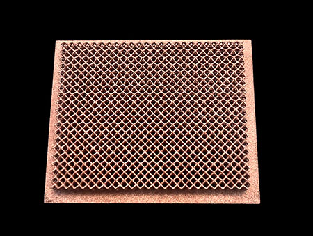
Let’s cut straight to it: if you design high-speed optical transceivers, thermal management is the silent bottleneck holding your performance back. As we push to 800G, 1.6T, and beyond, power densities keep climbing — but the package size stays exactly the same. A few extra degrees at the die, and you’re looking at degraded signal integrity, higher bit error rates, and shorter service life.
Traditional cooling methods only get you so far. Die-cast aluminum housings conduct heat poorly. Glued-on heat sinks add thermal interface resistance right where you can least afford it. And you can only fit so many machined fins into a tiny transceiver footprint before you run out of space.
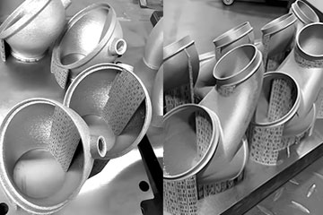
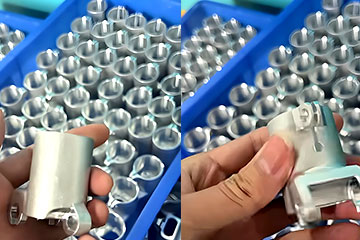
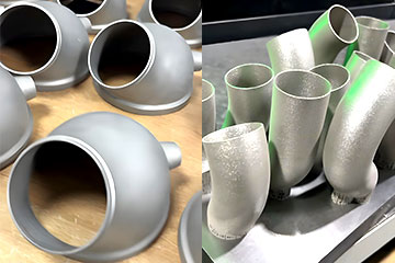
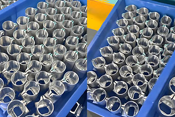
That’s where 3D printed pure copper thermal structures come in. We build compact, precision cooling features directly integrated into the module housing or heat spreader, with fine micro-fins and mini lattice structures you could never make with traditional tooling. The result: lower die temperatures in the exact same package size, no full redesign required.
On this page, we’ll break down how 3D printed copper cooling works for optical modules, what real temperature gains you can expect, and why more photonics teams are switching from cast and machined designs. This is part of our full lineup of 3D printed copper & copper alloy thermal management solutions, so you can see how optical module cooling fits into the bigger picture.
Why Traditional Optical Module Cooling Falls Short
If you’ve worked on high-speed transceiver design, you know the drill: you’ve got a tight form factor, a set of hot TOSA (Transmitter Optical Sub-Assembly) / ROSA (Receiver Optical Sub-Assembly) dies, and nowhere near enough room for a proper cooler.
The standard approaches all have hard limits:
- Die-cast aluminum housings are cheap, but aluminum’s thermal conductivity is only about 40% of pure copper — mediocre at best for high-density packages. Heat builds up at the source instead of spreading out across the housing.
- Bonded heat spreaders add a layer of thermal interface material between the die and the cooler. That interface resistance eats into your cooling performance, and over time, adhesive can degrade with thermal cycling.
- Machined fin structures work, but only to a point. Machining can’t produce fine enough features in such a small space to deliver the surface area you need for high-power dies.
- All of them force a one-size-fits-all approach. You can’t target cooling exactly at the hot spots; you’re stuck spreading heat evenly across a flat base, wasting valuable cooling capacity.
For 100G and 400G modules, you could fudge it and still hit specs. For 800G and 1.6T? That approach doesn’t cut it anymore.
How 3D Printed Pure Copper Solves Optical Module Thermal Headaches
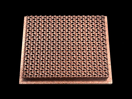
3D printing lets us build ultra-compact copper cooling structures with a level of detail and integration no traditional process can match. Instead of assembling multiple parts, we print the thermal structure — and often the entire module housing core — as one single solid piece.
Here’s what that actually delivers for your optical design:
Integrated structures eliminate interface resistance
The biggest win is also the simplest: we can build the cooling features directly into the part that sits against your die. No adhesive, no thermal pad, no bonded joint. Heat moves straight from the chip into the copper structure with zero extra resistance at the interface.
In real-world builds, that alone usually drops core temperatures by 2–3°C — before we even add optimized fin or lattice geometry.
Micro-fins and mini lattices for maximum surface area
We reliably print 0.2mm thin fins and sub-millimeter TPMS lattice structures inside even the smallest module footprints. That lets us pack far more heat transfer surface into the same space than any machined or cast design.
More surface area = more heat dissipated, in the exact same package outline. You don’t have to grow the module size or redo your PCB layout to hit thermal targets. We break down the full performance of these tiny lattice structures in our guide to TPMS lattice porous cooling structures.
Conformal cooling matched exactly to your die layout
No more flat, uniform heat spreaders that waste cooling on cool areas of the package. We can design thicker cooling features, targeted fin arrays, or directed heat paths right over the hottest TOSA/ROSA dies, and thinner structures where heat is lower.
The result: better temperature uniformity across the entire module, and peak temperatures that stay well within spec even at full load.
Drop-in fit for standard package footprints
We design every part to match your existing module outline, mounting holes, and board clearance. This isn’t a ground-up redesign — it’s a drop-in thermal upgrade that slots right into your current mechanical design. Most teams see a 4–6°C drop in core temperatures without changing anything else about their package.
Why Pure Copper Is The Default Pick For Optical Modules
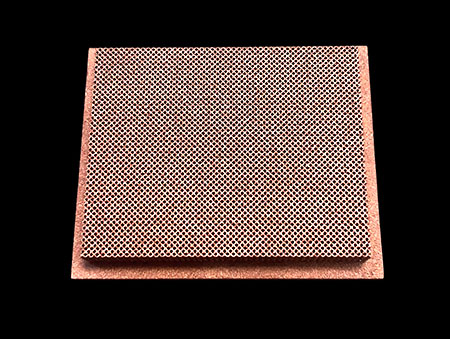
For almost all optical module builds, pure copper is the clear choice — and it’s not even close.
At 390–410 W/m·K, pure copper delivers maximum thermal conductivity, which is exactly what you need when you’re trying to pull heat out of a tiny, high-density package. Since optical transceivers operate in static, low-vibration environments inside data centers or telecom racks, you don’t need the extra mechanical strength of a copper alloy.
Pure copper is also easier to plate and finish for EMI shielding and corrosion resistance, which is critical for high-speed optical packages.
If you do have special requirements for higher structural strength or harsh-environment operation, we can also build these structures in copper alloys like CuCrZr. We walk through the full tradeoffs in our pure copper vs copper alloy 3D printing comparison guide.
Don’t just take our word for the temperature gains — photonics and optical engineering teams already use these copper structures to hit their thermal targets for high-speed transceivers. Here’s what our B2B clients say.
해외 B2B 고객들의 추천사

“무슨 안 좋은 일이 생길까 봐 정말 걱정되었습니다. 하지만 제품을 수령한 후, 제 걱정은 전혀 불필요한 것이었음을 알게 되었습니다. DT 3D Printing은 품질이 보장된 매우 신뢰할 수 있는 공장입니다.”

“제품 품질은 최고입니다 – notch, 장인 정신이 돋보입니다, 인쇄 효과가 훌륭합니다, 배송 속도가 정말 빠릅니다. 전체적으로, 가격 대비 훌륭한 가치를 제공합니다, 그리고 저는 매우 만족합니다.”


“인쇄 품질이 정말 훌륭합니다, 그리고 가격은 꽤 합리적입니다. 물류 처리 속도도 빠릅니다. 종합하자면, DT는 신뢰할 수 있는 공장입니다, 그리고 앞으로도 그들과 지속적으로 협력해 나갈 것입니다.”



Built For Real-World High-Speed Optical Applications
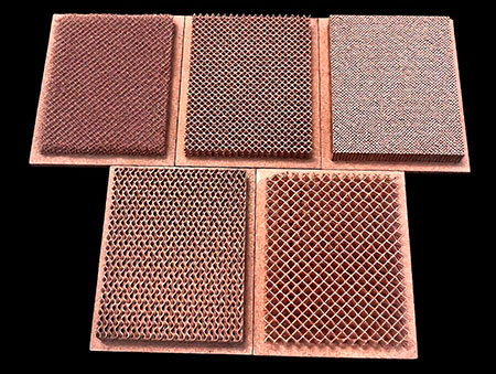
These aren’t lab-only prototypes. We print production-grade copper thermal structures for every major high-speed optical use case:
800G & 1.6T Pluggable Transceivers
QSFP-DD, OSFP, and other small form-factor pluggables run extremely hot at full bandwidth. Our integrated copper cooling structures help you hit temperature specs without increasing package size or forcing power derating.
TOSA & ROSA Thermal Management
Laser dies and receiver arrays are the hottest, most temperature-sensitive parts of any module. We build targeted cooling structures that pull heat directly from these components, stabilizing output power and reducing signal drift.
Coherent Optical Modules
Coherent modules pack more processing power and higher heat density into the same footprint. Our lattice-enhanced copper structures deliver the extra cooling capacity needed to keep performance consistent across operating temperature ranges.
Data Center & Telecom Line Cards
For on-board optical engines and line card assemblies, we design custom copper heat spreaders and integrated cooling structures to handle multi-module heat loads in tight rack spaces.
The Big Myth: “Small Modules Don’t Need High-Performance Cooling”
Let’s bust this one right now: smaller package size does not mean less cooling demand. If anything, it’s the opposite.
High-speed optical modules pack serious power into a tiny volume. That power density — watts per cubic centimeter — is often higher than much larger electronic components. Hot spots get hotter, heat has nowhere to go, and even a small temperature rise directly impacts laser performance, bit error rate, and long-term reliability.
Cheap cast aluminum cooling might get you past a bench test, but it won’t hold up across the full operating temperature range over a 5–10 year service life. For 800G and faster modules, high-performance copper cooling isn’t a luxury — it’s table stakes for hitting reliability specs.
자주 묻는 질문
Can you match standard optical module form factors?
Absolutely. Most clients come to us with an existing QSFP, OSFP, or custom package outline, and we design the cooling structure as a drop-in replacement. No full mechanical redesign required.
How small of features can you print for module-sized parts?
For production-grade optical structures, we reliably hit 0.2mm wall thickness and 0.15mm diameter lattice struts for appropriately sized structures. We always run a DFM review upfront to confirm your features are manufacturable at consistent quality.
How much temperature reduction can we expect?
It depends on your starting design and power level, but most teams see a 4–6°C drop in peak die temperature compared to a standard cast aluminum housing with similar footprint. In some cases with full lattice optimization, we’ve seen even larger gains.
How long do prototype parts take?
For standard prototype builds, we typically turn around first articles in 10–15 business days after design finalization. Production lead times scale with order quantity, and we’ll give you a firm timeline with your quote.
Do you offer design support for optical thermal structures?
네. Our engineering team can work with your thermal specs and package constraints to optimize cooling geometry for your exact die layout. We don’t just print what you send us — we help you make it better. For comprehensive best practices, check out our design guide for 3D printed copper heat exchangers.
Ready To Knock Down Your Optical Module Thermal Bottleneck?
If you’re struggling to hit temperature specs on your next high-speed transceiver design, or you’re looking to squeeze more performance out of an existing package, let’s talk.
Send us your package outline, heat load specs, and target temperatures, and our engineering team will get back to you with:
- A full DFM (Design for Manufacturing) review
- A clear recommendation on structure type and material
- Expected temperature reduction estimates
- Firm pricing and lead time
No generic sales pitches, just straight engineering feedback from people who build copper cooling for optical modules every day.
Request your free design review today and get your thermal specs on track.
Keep exploring
- Pure Copper 3D Printing Technology for Advanced Thermal Management
- Pure Copper vs Copper Alloy 3D Printing: Full Comparison
- TPMS Lattice Porous Structures for Next-Gen Copper Cooling
- Design Guide for 3D Printed Copper Heat Exchangers


회사 소개
1. We are a professional metal 3D printing manufacturer.
2. 당사는 자동차용 금속 부품을 3D 프린팅합니다., 의료, 항공기, 항공우주, 드론, 및 선박 산업, 스테인리스강과 같은 재료를 사용하여, 티타늄, 구리, 알루미늄과 합금의 종류.
3. 원스톱 3D 프린팅 서비스를 제공합니다.
당사의 서비스에는 다음이 포함됩니다:
SLM / BJ / SLA / MJF / FDM / SLS / DLP, CNC machining and post-processing
4. 저희는 33 SLM 금속 3D 프린터, 14 CNC machining tools, 60 플라스틱 3D 프린터, 50 BJ 3D printers (owned by another company in which DT has invested), 그리고 그 숫자는 계속 늘어나고 있습니다.
5. We are a source factory for many global 3D printing service providers.
왜 저희를 선택해야 할까요??
- We have manufactured numerous pure cooper and cooper alloy thermal management components via 3D printing using copper and copper alloys for clients all over the world.
- 당사는 다음과 같은 서비스를 제공합니다. 자체 생산 with 33 high-end industrial SLM metal 3D printers, 14 CNC machines and 50 industrial BJ 3D printers (Owned by another factory in which we have an investment).
- 신규 고객을 위한 특별 혜택
- SLM 금속 프린팅이 바로 저희의 강점입니다. 저희는 33 프리미엄 SLM 금속 3D 프린터, 대부분의 가격은 약 $150,000 각, 그리고 저희 차량 대수는 여전히 늘어나고 있습니다.
- 최소 주문 수량(MOQ) 없음 (최소 주문 수량) 필수. 단 한 건의 콘텐츠라도 고객님께 맞춰 맞춤 제작해 드립니다..
문의 사항이 있으시면 언제든지 연락해 주십시오..
최소 주문 수량(MOQ)은 없습니다. (최소 주문 수량) 여기까지. 단 한 건의 콘텐츠라도 고객님께 맞춰 맞춤 제작해 드립니다..
상담에 오신 것을 환영합니다.